
This video demo demonstrates the SMSM with sample playback, amplitude modulation, bass mode, pitch bend and noise channel control using the SN76489 PSG sound chip.
If you enjoy this post, please like my Facebook page or follow this blog for future SMSM updates.
Overview
This post marks the release of the SEGA Master System MIDI Interface (SMSM) device, as well as the release of the SMSM v100 firmware.
The code etc for this is open and free to use. Please do not commercialise this. It is not for making money. It is for making cool chiptune musics. I encourage you to build one of these. It is easy and shouldn't take long. I encourage you to hack the code and play and have fun with it.
SMSM is an interface that takes MIDI data and controls the sound chip inside of the SEGA Master System in real time. The idea is to send MIDI data to the SEGA Master System using a MIDI sequencer or MIDI keyboard via the SMSM, which then sends the appropriate audio signal out of the console via its AV port or a direct output port.
So for example, if a MIDI note C is sent to the SMSM, then the SEGA sound chip will play a tone with pitch of a C. The PSG SN76489 sound chip is supported as well as the FM YM2413 sound chip (which is found in Japanese models of SEGA Mater System).
The aim of this post is to cover the simplest hardware setup that can be used to create an SMSM interface. This is achieved via a Arduino Serial setup. Other methods are possible too.
The SMSM is made up of two parts:
1) A microcontroller-based interface that takes MIDI data and connects to port 2 of the SEGA Master System and;
2) A SEGA Master System cartridge running a custom program
In this blog post, the microcontroller-based interface is an Arduino UNO running as a USB Serial connection via a software MIDI to Serial layer. If that sounds confusing, simply read through this blog post and follow the instructions.
It is important to note that the microcontroller-based interface could take other forms, such as a native USB MIDI device or a native 5-pin DIN MIDI device.
If you would like me to send you a custom EPROM with the SEGA Master System software on it so that you can make your own cartridge, please email me at seb.tomczak@gmail.com. The EPROMs cost roughly AUD$7 or so (plus postage).
Important Additional Points
• The SMSM interface is also compatible with the SEGA Game Gear. A tutorial can be found here.
• The post you are currently reading is for the Arduino Serial version. You can also use a traditional MIDI 5 pin DIN connection if you like, although this is slightly more complex from a hardware perspective. Please view this tutorial for more information.
• The SMSM is PAL by default. If you are using an NTSC console, please view this simple modification tutorial.
MIDI Mapping
MIDI channels 1 - 4 are mapped to the SN76489. MIDI channels 5 - 14 are mapped to the YM2413. Most Western SEGA Master Systems feature only the SN76489. Japanese SEGA Master Systems feature both the SN76489 as well as the YM2413. It is possible to add a sound chip to a SEGA Master System console that is missing the YM2413, as seen in this thread.
The full MIDI mapping of SMSM firmware v100 can be found here: http://little-scale.com/SMSM/SMSM_100/SMSM_100_MIDI_Mapping.txt
Quickstart: Arduino Software
The code for the micrcocontroller-based interface can be downloaded here: http://little-scale.com/SMSM/SMSM_100/SMSM_100_Arduino_Serial.ino
Note that this is the "Arduino Serial" version of the firmware, and requires a baud rate of 57600 and a Serial port connection on a host computer. The MIDI2Serial Max Patch or OS X application can be used to this end.
Quickstart: Arduino Hardware
The link between the Arduino and the SEGA Master System is via controller port two, as follows:
SMS Player 2 Port Pin 1 to Arduino Pin 2
SMS Player 2 Port Pin 2 to Arduino Pin 3
SMS Player 2 Port Pin 3 to Arduino Analog Input Pin 0
SMS Player 2 Port Pin 4 to Arduino Analog Input Pin 1
SMS Player 2 Port Pin 5 No Connection
SMS Player 2 Port Pin 6 to Arduino Analog Input Pin 2
SMS Player 2 Port Pin 7 to Arduino Pin 4
SMS Player 2 Port Pin 8 to Arduino Ground
SMS Player 2 Port Pin 9 to Arduino Analog Input Pin 3
The controller port connector should be a female connector, and the pins are as follows (looking at the connector from the front). You can splice a SEGA controller cable, or buy a DB9 connector from an electronics store.

Quickstart: SEGA Cartridge Software
The ROM for the SEGA Master System can be downloaded here: http://little-scale.com/SMSM/SMSM_100/SMSM_100_ROM.sms. The source code for the ROM can be downloaded here: http://little-scale.com/SMSM/SMSM_100/SMSM_100_Source_Code_Z80.txt.
Quickstart: SEGA Cartridge Hardware
You can either make your own SEGA cartridge, or you can buy a SEGA flashcart (such as here).
If you want to make your own SEGA cartridge, you can either get a PCB made, or you can hack an old SEGA game (see below for a step-by-step).
If you would like me to send you a custom EPROM with the SEGA Master System software on it so that you can make your own cartridge, please email me at seb.tomczak@gmail.com. The EPROMs cost roughly AUD$7 or so (plus postage).
Step-by-Step: How to Make the SMSM Micrcontroller-Based Interface (Arduino Serial Version)
Parts needed:
• SEGA controller (for cable splicing)
• Arduino UNO or similar micrcontroller board
• Small strip / vero board
• 10 pin header (only 9 pins needed)
• USB A to B cable
• SEGA Master System
• Home made SEGA Master system EPROM / EEPROM / Flash cartridge
• OR SEGA Master System Flash cartridge
• Breadboard, Breadboard jumpers
• Soldering iron, Solder, Soldering helping hands, Solder cleaner, Wire stripppers, Multi-meter
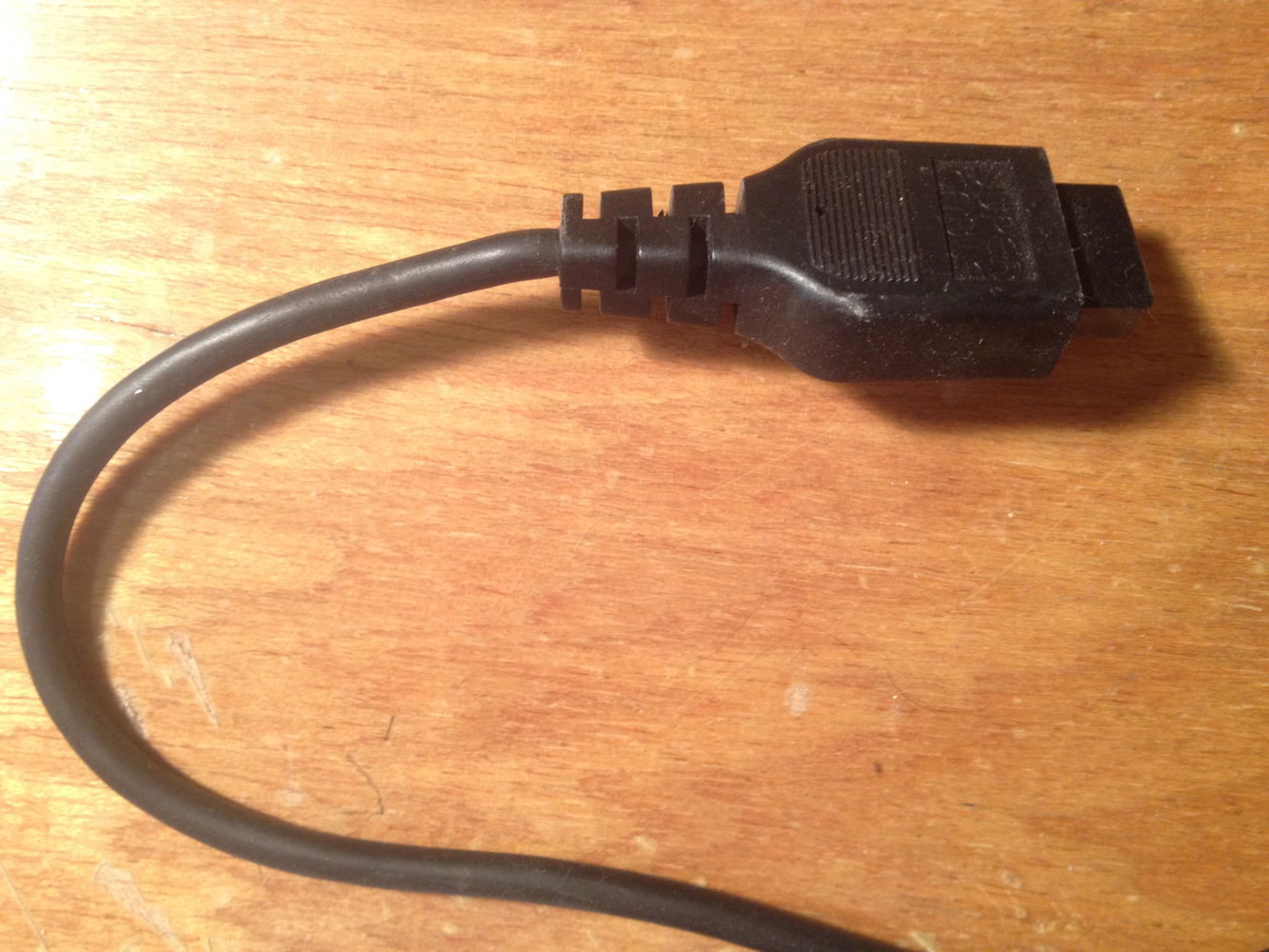
1. Take the SEGA controller and cut off the connector. Strip back the insulation.


10. Place the ten pin header in the board, so that each pin has its own vertical strip.


A Live demo track can be downloaded here: http://little-scale.com/SMSM/SMSM_100/SMSM_100_demo.alp
A Live template can be downloaded here: http://little-scale.com/SMSM/SMSM_100/SMSM_100_template.alp
Step-by-Step: How to Make a 32KB Sega Cartridge
If you would like me to send you a custom EPROM with the SEGA Master System software on it so that you can make your own cartridge, please email me at seb.tomczak@gmail.com. The EPROMs cost roughly AUD$7 or so (plus postage).
These carts have been tested on a PAL SMS 1 and a PAL SMS 2.
The good news is that the cartridges use a re-programmable EPROM, provided that you have the appropriate facilities (EPROM programmer and EPROM eraser).
This tutorial would not have been possible without the Sega Master System cartridge port connector pinouts as found one Maxim's page: http://www.smspower.org/maxim/docs/pinouts.html. Maxim's webpage is an excellent resource for all things that are related to the Sega Master System, and I would like to thank him for the amount of effort and time he has put into creating it.
After the step-by-step section, there is a pinout for the cartridge PCB.
 1.
You will need a 27C256 EPROM chip. In this tutorial, I use an ST
Microelectronics 27C256B chip. If you are using your own EPROM
programmer, ensure that the programmer is able to write to both the
EPROM model and manufacturer type. This should be documented within the
programming software that came with your programmer or with any relevant
printed documentation.
1.
You will need a 27C256 EPROM chip. In this tutorial, I use an ST
Microelectronics 27C256B chip. If you are using your own EPROM
programmer, ensure that the programmer is able to write to both the
EPROM model and manufacturer type. This should be documented within the
programming software that came with your programmer or with any relevant
printed documentation. 2.
You will need a Sega Master System cartridge. In particular, we are
looking for a cartridge with a single chip on the board. This chip
should be a wide-body chip with 28 pins. The printed circuit board that I
have used so far is the model 171-5519. I have found the correct chip
size and printed circuit board in AUS PAL versions of The Ninja, World Grand Prix and F-16 Fighter, all of which are fairly common. This tutorial should work with many other games as well.
2.
You will need a Sega Master System cartridge. In particular, we are
looking for a cartridge with a single chip on the board. This chip
should be a wide-body chip with 28 pins. The printed circuit board that I
have used so far is the model 171-5519. I have found the correct chip
size and printed circuit board in AUS PAL versions of The Ninja, World Grand Prix and F-16 Fighter, all of which are fairly common. This tutorial should work with many other games as well. 3.
You will need a 28 pin, wide body socket. However, I did not have any
handy at the time and my local electronics shop had run out of stock.
So, I used a 40 pin wide body socket instead.
3.
You will need a 28 pin, wide body socket. However, I did not have any
handy at the time and my local electronics shop had run out of stock.
So, I used a 40 pin wide body socket instead. 4. Remove the two screws on the back of the cartridge. Inside you will find the cartridge circuit board.
 5.
Check that the board only has one chip on it, and that that chip is a
28 pin, wide body chip. There should also be a ceramic capacitor in the
top left and an electrolytic capacitor on the right side of the board.
5.
Check that the board only has one chip on it, and that that chip is a
28 pin, wide body chip. There should also be a ceramic capacitor in the
top left and an electrolytic capacitor on the right side of the board. 6.
Carefully desolder the chip. I usually use a vaccum solder pump for
this sort of thing, because it is quite quick but it is not always 100%
reliable (ie. sometimes a point must be worked on more than once before
enough solder is removed). Perhaps you feel more comfortable with
desoldering braid.
6.
Carefully desolder the chip. I usually use a vaccum solder pump for
this sort of thing, because it is quite quick but it is not always 100%
reliable (ie. sometimes a point must be worked on more than once before
enough solder is removed). Perhaps you feel more comfortable with
desoldering braid. 7. Here you can see the front of the board with the missing chip.
 8. You will need to cut off the bottom six legs of each side if you are using a 40 pin socket like me.
 9. Here you can see the 40 pin socket with the 12 legs removed.
 10. You may need to bend the ceramic capacitor in the top left hand corner to the left.
 11. This way, the top of the socket has room to fit correctly in place.
 12.
If you are using a 40 pin socket like me, you may need to move the
electrolytic capacitor in the middle right hand side of the board over a
touch.
12.
If you are using a 40 pin socket like me, you may need to move the
electrolytic capacitor in the middle right hand side of the board over a
touch. 13. This way, the bottom of the socket has enough room to fit correctly in place.
 14.
Place the socket on to the front face of the board, so that the twelve
legs that were cut off earlier are on the right hand side of the board
(if you are using a 40 pin socket like me). The stubs of the cut off
legs should not touch the surface of the circuit board (if you are using
a 40 pin socket like me).
14.
Place the socket on to the front face of the board, so that the twelve
legs that were cut off earlier are on the right hand side of the board
(if you are using a 40 pin socket like me). The stubs of the cut off
legs should not touch the surface of the circuit board (if you are using
a 40 pin socket like me). 15. Here you can see the socket sitting in place from the back of the board.
 16. Solder the socket into place.
 17.
If your EPROM has been used before, you will need to erase it. For my
ST 27C256 EPROM, I set my erase timer to 10 minutes. The amount of time
required to erase your particular EPROM might be different, depending on
the manufacturer.
17.
If your EPROM has been used before, you will need to erase it. For my
ST 27C256 EPROM, I set my erase timer to 10 minutes. The amount of time
required to erase your particular EPROM might be different, depending on
the manufacturer. 18.
Program the EPROM with the (legal) ROM of your choice. In my case, I am
programming a homebrew test program. I am using a TOP2007 general
programmer, which is USB powered - quite convenient. However, I did have
to install the latest software from their website in order to be able
to program the 27C256 without errors.
18.
Program the EPROM with the (legal) ROM of your choice. In my case, I am
programming a homebrew test program. I am using a TOP2007 general
programmer, which is USB powered - quite convenient. However, I did have
to install the latest software from their website in order to be able
to program the 27C256 without errors. 19.
Gently place the EPROM into its socket. You may need to gently change
the angle of the pins, so that they align with the socket correctly.
19.
Gently place the EPROM into its socket. You may need to gently change
the angle of the pins, so that they align with the socket correctly. 20. Enjoy your cartridge.
 21.
You may also like to solder your EPROM onto the board directly, as
shown above. If so, do so gently and make sure you apply the soldering
iron to the legs of the EPROM for short amounts of time only. The
disadvantage of using a soldered EPROM is that you can only really
program it one time.
21.
You may also like to solder your EPROM onto the board directly, as
shown above. If so, do so gently and make sure you apply the soldering
iron to the legs of the EPROM for short amounts of time only. The
disadvantage of using a soldered EPROM is that you can only really
program it one time. 23. The advantage is that it can fit inside an old cartridge shell.
Cartridge PCB Pinout
If you are interested in the pinout of the IC socket compared to the Sega Master System port, then this photo can help you.
 The
IC socket shares the same pins for both the front and the back (of
course) but the edge connector that mates with the actual Sega Master
System has two sides. The front side has the even numbers from 2 to 50
and the back side has the odd numbers from 1 to 49. This pinout is of
course only relevant to boards that have a single, wide body 28 pin ROM
chip on them to begin with.
The
IC socket shares the same pins for both the front and the back (of
course) but the edge connector that mates with the actual Sega Master
System has two sides. The front side has the even numbers from 2 to 50
and the back side has the odd numbers from 1 to 49. This pinout is of
course only relevant to boards that have a single, wide body 28 pin ROM
chip on them to begin with.The front side is the one where the ROM chip faces upwards, and the face of the front points towards the front of the Sega Master System when inserted into the console.
As one can see below, the pinouts of the socket on the PCB when compared to the SMS cartridge port in light of using a smaller size EPROM (i.e. 32KB) works out very nicely, and no changes or rewiring are required.
EPROM   CART    FUNCTION
1       2       CART: !W; EPROM: VPP
2       33      A12
3       32      A7
4       31      A6
5       30      A5
6       29      A4
7       28      A3
8       27      A2
9       26      A1
10      25      A0
11      24      D0
12      23      D1
13      22      D2
14   19,20,21 0V

EPROM   CART    FUNCTION
28      1,35    5V
27      6       A14
26      7       A13
25      8       A8
24      9       A9
23      10      A11
22      11      CART: !M0-7; EPROM: !OE
21      12      A10
20      13      !CE
19      14      D7
18      15      D6
17      16      D5
16      17      D4
15      18      D3

4 comments:
Hello Seb,
I haven't had the chance to build the arduino side of this interface but I did manage to make my own flash cart. The EEPROM burned and all seemed successful. Will I be able to test the cart with the SMS or will the cart not function until the Arduino side is connected? Right now the SMS just holds at the SEGA 1988 Blah blah screen.
Can't believe there are no comments on this. You are my hero.
Hey,
If anyone's trying to compile the midi in code you need to replace: prog_uchar with const byte, otherwise it won't work!
Hey,
If anyone's trying to compile the midi in code, you need to replace 'prog_uchar' by const char!
Thank you for the awesome tutorial :)
Flo
Post a Comment